LISP Programs. Inventory of green spaces Saving the program code on your computer
The concept that the company is guided by is the priority of quality in everything due to compliance with the requirements of the modern market, continuous improvement of the effectiveness of the management system, quality and monitoring of completed projects
Inventory, accounting of green spaces, entering inventory data into the AIS "Register of green spaces" in Moscow, making a "Territory Improvement Passport"
Primary activity inventory of green spaces, accounting for green spaces, making passports for improvement of the territory, entering data into the AIS Register of green spaces, approval of the passport for improvement of the territory in the JKKHiB and DPiOOS.
We have been taking inventory and certification of green spaces and road facilities in Moscow for 9 years.
During this time, we have inventoried about 5,000 hectares:
Landscaped areas 1,2,3 content categories,
Forests, parks, squares, roads, courtyards, incl.
Alexander Garden (garden near the Moscow Kremlin),
Kremlin embankment, green areas on Red Square near GUM,
Novy Arbat, Pokrovsky Cathedral, shopping and entertainment complex "Manezh",
Solntsevo district, Vernadsky Avenue district, Dorogomilovo district, Troparevo-Nikulino district,
District Vykhino-Zhulebino, Lefortovo, Maryino, Nekrasovka, Ryazansky
Southern Administrative District,
South-Eastern Administrative District,
Districts of New Moscow (TiNAO),
Squares and parks of the Central Administrative District,
Green areas along the Moscow Ring Road,
Green areas along the Third Ring Road,
Vnukovo Airport,
All-Russian Dispatch Center Vnukovo,
All radial highways in Moscow (Shchelkovskoye highway and Entuziastov highway, Altufevskoye and Yaroslavskoye highways, Kashirskoye and Varshavskoye highways, Mozhayskoye and Rublevskoye highways, Volokolamskoye and Zvenigorodskoye highways, Mezhdunarodnoe highway, Kievskoye highway, etc.)
A large number of hospitals, polyclinic (GBUZ), schools (GBOU), industrial and commercial territories, and this is not an exhaustive list of territories that we have stockpiled.
Grounds for performing work on the inventory of green spaces in Moscow:
Decree of the Moscow Government dated August 12, 2014 No. 461-PP “On the automated information system“ Register of green spaces ”(as amended on October 4, 2017)”;
Decree of the Moscow Government dated September 10, 2002 N 743-PP (as amended on October 4, 2017) "On approval of the Rules for the creation, maintenance and protection of green spaces in the city of Moscow";
Decree of the Moscow Government dated September 2, 2014 No. 501-PP "On the development of passports for the improvement of courtyard areas, amending the legal acts of the city of Moscow and invalidating the legal acts of the city of Moscow";
Law of the city of Moscow dated 05.05.1999 No. 17 "On the protection of green spaces" (as amended on May 7, 2014).
The inventory of the territories of the green fund of the city of Moscow is carried out in order to:
Obtaining reliable data on the state of green spaces, species, age composition, on the quantitative and area characteristics of natural communities, elements of integrated improvement for urban management at all levels of management, operation and financing;
Obtaining information on the location of green spaces, elements of complex improvement on the territory of the green fund of the city of Moscow, indicating the rights holders of land plots of the territory responsible for its safety and condition;
Determination of the conformity of the activities carried out by the rightholders of the land plots of the territory of the green fund of the city of Moscow at the greening objects, the established purpose of the territories;
Analysis of the state of the green fund of the city of Moscow;
Determination of land plots occupied by various types of plantations, infrastructure or other elements in their composition;
Information support for the preparation of planning projects for natural, specially protected natural (hereinafter - SPNA) (for which there are no plans for planning), specially protected green areas (hereinafter - SPNT), green areas and other areas occupied by green spaces in the city of Moscow;
Development of measures for the preservation and restoration of natural communities and recommendations for the management of land plots; infrastructure and improvement elements in specially protected natural and other natural areas for the revision period for the management of the State Budgetary Institution "Moscow City Administration of Natural Territories";
Determination of the effectiveness of reforestation work, the quality state of the created forest cultures, their compliance with the current standards and technical conditions. These materials make it possible to determine measures to improve the condition of crops;
Development of proposals for adjusting plans for the planning of protected areas, natural, green areas and other areas occupied by green spaces, the city of Moscow, territorial schemes for the development of protected areas in the city of Moscow;
Regulation of work and determination of costs for the preservation and maintenance of natural communities, green spaces, elements of landscaping and complex improvement and overhaul on the territory of the green fund of the city of Moscow (based on the obtained characteristics of the state of elements of landscaping and complex improvement);
Drawing up a title list for green spaces, elements of landscaping and complex improvement for the calculation of natural indicators for the territories of the green fund of the city of Moscow;
Preparation of data for filling the State cadastre of protected areas of the city of Moscow, the Automated Information System "Register of Green Spaces", the Automated Control System "United Dispatching Service of the Department of Housing and Communal Services and Improvement of the City of Moscow" (hereinafter - ACS "ODS DZHKHiB"), other information systems of the city Moscow, if such is established by the legislation of the Russian Federation and the city of Moscow.
Types of work on certification of green spaces:
1.Conducting preparatory work
Obtaining the boundaries of the inventory territory;
Reconnaissance survey of the inventory area;
Establishment of the area of the inventory territory;
Establishing the classification of the inventory object
Determination of the location of trees in nature in the inventory territory;
Determination of the location of the bush in nature in the inventory territory;
Collection of general information about the inventory area (including administrative-territorial affiliation;
Indication of the responsible land user;
Establishing the status of the object, the functional purpose of the land plot;
2.Conducting field work on inventory of green areas:
Geodetic survey of the inventory area using geodetic equipment and local measurements;
Determination of woody vegetation in kind, numbering in kind, measurement of diameter, age, height, description of the state;
Determination of shrub vegetation in kind, numbering in kind, measurement of diameter, age, height, description of the state;
Determination of the condition of lawns, measurement of the area, description of quality characteristics, determination of the type of lawn;
Description of flower beds, measuring the area, assigning a serial number, determining the type of flower garden, planted plant material;
Description of the road and path network, determination of the condition, type of coverage, purpose, measurement of the area;
Determination of the location of the LFA and improvement elements, their quantity, numbering, characteristics and description of the state;
Definition of buildings and structures in the inventory area, their purpose and area measurement;
Determination of plane structures, their type, area and coverage;
Determination of the elements of the organization of the relief, their type, area;
Determination of functional support systems, their type and number;
Collection of information about repair work;
Collection of additional information (date of the last repair or reconstruction, mode of urban planning activities);
3.Conducting office work on inventory of green areas:
Creation of an inventory plan of the object M1: 500, with registration in accordance with the decree of the Moscow Government dated 04.10.2005, No. 770-PP "On methodological recommendations for drawing up dendrological plans and counting lists";
Applying trees and shrubs to the plan with the assignment of ordinal numbering in accordance with the list of green spaces;
Calculation of the total area of the object, and entering data into the statement;
Drawing flower beds on the plan, calculating their areas and entering into a statement;
Drawing on the plan of buildings and structures, calculating their areas and entering them into a statement;
Calculation of the operational area of the object and entering the data into the statement;
Drawing planar structures on the plan, calculating their areas and entering them into a statement;
Drawing on the plan of the road and path network, calculating its areas and entering into the statement;
Drawing a lawn on a plan, calculating areas and entering into a statement;
Drawing on the LFA plan, miscalculation by quantity and entering into the statement by type;
Drawing on the plan of functional support systems, miscalculation by quantity and entering into a statement by type;
Drawing on the plan of the elements of the organization of the relief, calculating the areas and entering into the statement;
Data collection and printing of field records on a computer;
Calculation of the total number of trees in the facility;
Calculation of the total number of shrubs on site;
Calculation of transplanted trees on site;
Calculation of transplanted shrubs on site;
Calculation of cut trees at the facility;
Calculation of cut down shrubs on site;
Calculation of the stored trees on the object;
Calculation of preserved shrubs on site;
Drawing up the balance of the territory;
4. Conduct cartographic works:
Ensuring electronic registration of landscaping objects and green spaces when maintaining AIS "Register of green spaces" and monitoring green spaces;
Drawing up a topographic plan in electronic form with reference to the Unified State Cartographic Framework of the City of Moscow in formats that provide free import of data into geographic information systems;
Registration of an inventory plan in accordance with the existing requirements M1: 500;
Approval of the Territory Improvement Passport in electronic form in the Department of Housing and Communal Services and the Department of Natural Resources and Environmental Protection.
We are proud of the work done, because our main principle in any work is honesty, integrity, and love for the business you are doing.

Completed projects
News: 2 April 2015 New requirements for approvals of the Territory Improvement Passport Instructions on how to approve the Customer's passport in the Register. 30 March 2015 Clarifications on changes in the requirements for passports for the improvement of the territory (accounting area) In the passport of the accounting site, the name (Passport of the territory improvement) and the procedure for approval have changed. 29 March 2015 For a green space passport. From Decree N 743-PP dated 12.12.2014. Methodology for conducting an inventory in the territories of the green fund of the city of Moscow Published information from the decree on the methodology of inventory of green spaces in Moscow March 29, 2015
Examples of LISP programs will be posted on this page. Many of them have tutorials with detailed code descriptions.
If you know how to run in AutoCAD, you can immediately
How to use the programs.
All programs are written for use in the full version of AutoCAD. They will not work in AutoCAD LT.
If you liked any program on this site and you want to install it on your computer. To do this, you need to do the following:
1. Download the program to your computer;
2. All programs are archived. Therefore, after you have downloaded the archive, you need to unzip it. Having unzipped the archive, you will receive the program files that you can store anywhere on your computer (I use the D: \ MyLisp folder for this);
3. Program files must be loaded into AutoCAD;
4. Run new commands that are stored in the downloaded files.
I think everyone can handle the first two points. Therefore, let's immediately talk about loading LISP files into AutoCAD.
Loading LISP files into AutoCAD.
You can load the program into AutoCAD LISP in several ways. I will describe some of them.
Download files using the "Load / Unload Applications" window.
Open AutoCAD. On the ribbon, go to the "Control" tab and click on the "Application" button. See Fig. 1.
Rice. 1 Application button
If you are working in Classic AutoCAD mode:
In the main menu, select "Service", then click on the line "Applications ...". See Fig. 2.
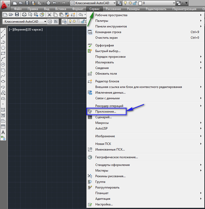
Rice. 2. The line "Application
Find the folder where the file is located, select it and click on the "Download" button. See Fig. 3.

At the bottom of the window, a message will appear stating that the selected file has been loaded. Please note that this method can be used to load not only LISP files (* .lsp), but also other applications supported by AutoCAD ( * .arx; * .crx; * .dvd; * .dbx; * .vlx; * .fas).
In this way, programs are loaded for temporary use. After you close AutoCAD, and then open it again, they will not be in AutoCAD, and to use them you need to download them again.
In order for the LISP files you need to be loaded into AutoCAD automatically, they need to be added to the automatic download list. To do this, click on the briefcase "" (or on the button "". See Fig. 4.

The Add File to Auto Startup List window appears. Find the required folder, select the file and click on the "Open" button. See Fig. 5.
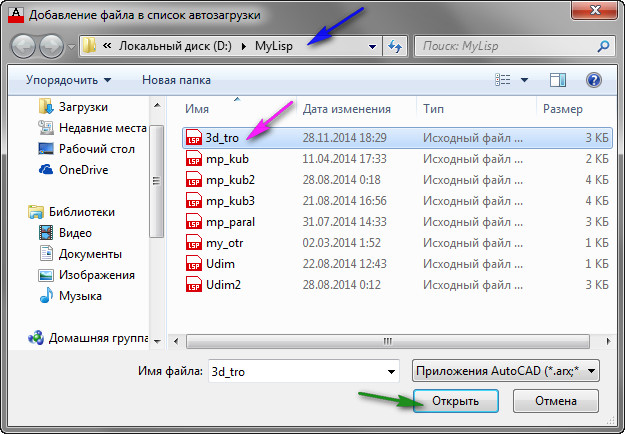
Rice. 5. Adding a file to the auto-download list
Which will be automatically loaded every time you start AutoCAD.
After you add all the necessary files, click on the "Close" button. Then click on the "Close" button in the "Load / Unload Applications" window. See Fig. 6.

Rice. 6. File added
Keep in mind that the files will be loaded automatically only the next time you start AutoCAD. If you want to use them in the current session, you need to download them in the way described above (or in some other way).
Uploading files using the Visual LISP Editor.
Open the Visual LISP Editor:
Type VLIDE (or VLISP) at the command line and press
Or go to the "Manage" tab on the ribbon and click on the "Visual LISP Editor" button. See Fig. 7.
Rice. 7. Visual LISP editor
The Visual LISP Editor will open. Click on the "Open File" button. The Open File for Editing / Viewing window appears.
Find the folder you want;
Select the file and click on the "Open" button. See Fig. eight.
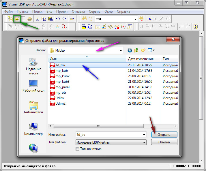
Rice. 9. Opening a file in the Visual LISP Editor
The file will be loaded into the active editor window. To load it into AutoCAD, you need to click on the button " Load active editor window».
This method has its advantages due to the fact that you see the program code of the file:
1. You can see how many commands are in this LISP file (there can be several of them).
2. Find the names of these commands: find the line with the defun function; The command name appears immediately after the c: (in our case, these are: 3d_tro and roY);
3. Among other things, you have the opportunity to edit the program code.
See Fig. nine.
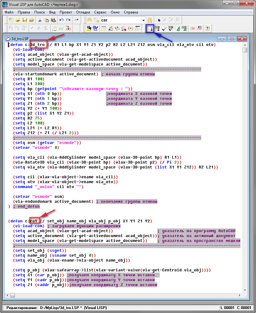
Rice. 9. Names of new teams.
To define the scope of a command in code, place the mouse cursor in front of the opening parenthesis of the defun function and double-click the left mouse button. The defun function, which describes one command - stand out. See Fig. ten.

Rice. 10. The program code of one command
Launching new commands.
After the files are loaded, we can run new commands in AutoCAD that are stored in these files. To do this, just type the COMMAND NAME in the command line and press
In addition, you can create a button for any command.
Place it on the toolbar, and place the panel on the ribbon.
After that, run the command by clicking on this button.
Read how to do this in the lessons: "" and "".
You can also create hotkeys for these commands and launch them by pressing specific keys on the keyboard.
Read how to do this in the lesson: "".
Of course, we have not covered all the ways to download files and run commands, but this is more fully enough to comfortably use the ones below.
List of LISP programs.
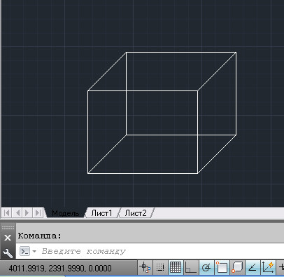
LISP program "mp_kub.lsp"
A program that draws a cube with sides 200 in AutoCAD.
To run in AutoCAD, the name MP_KUB is used
Pick a base point».
We indicate any point in the working window of AutoCAD. The team will build a cube with sides 200.

(File size: 449 bytes)
LISP program "mp_paral.lsp"
The program draws a parallelogram, with the sides specified in the dialog box. The program works only in conjunction with the "mp_paral.dcl" dialog file. Therefore, you need to download two files.
For AutoCAD to locate the dialog box file, it must be placed in the AutoCAD auxiliary files folder.
How to do this, see the lesson: "".
Or in the program code, in the line
(setq dcl_id (load_dialog "mp_paral.dcl")) you need to specify the full path to the file of the dialog box.
For example, if the file is located in the "D: \ MyLisp" folder, the line should look like this:
(setq dcl_id ( load_dialog "D: \\ MyLisp \\ mp_paral.dcl"))
To run in AutoCAD, the name MP_PARAL is used
After launch, a dialog box will appear on the screen.

You need to specify the dimensions of the sides of the parallelogram and click on the OK button.
We indicate any point in the working window of AutoCAD. The command will build a parallelogram with the sides specified in the dialog box.
For a detailed description of the program code, see the lesson: "".
For a detailed description of the program code for creating a dialog box, see the lesson: "".
(File size: 392 bytes)
(File size: 781 bytes)
LISP program "Sum_dl.lsp"
The program calculates the sum of the lengths of the selected segments. In the process of selecting segments, AutoCAD displays the number of selected segments and the sum of their length.
To run in AutoCAD, the name SumDl is used
Select line»:
Pick any line segment.
It will stand out. A message appears in the command line that one segment and its length are selected.
Select line»:
Pick the next line segment.
It will stand out. The command line will display a message about the number of selected segments and their total length.
The request will appear below again: “ Select line»:

The number of segments selected and their total length.
And so on ad infinitum. Press the key to end the program.
For a detailed description of the program code, see the lesson: "".
(File size: 464 bytes)
LISP program "Sum_dls.lsp"
The program of the sum of lengths with free choice of line segments.
The program calculates the sum of the lengths of the selected segments.
The selection of segments can be done either one at a time or in a group using a frame (or using a crossing frame). In general, any standard AutoCAD way.
To run in AutoCAD, the name is used: SumDls
Select objects»:
You can select segments in any standard way AutoCAD. If you accidentally select the wrong segment, you can deselect it. To do this, hold down the key
The process of selecting and deselecting line segments is reflected in the command line.

Cancels the selection of an object.
After you have selected all the required objects, click
The command line will display a message about the number of selected segments and their total length.

For a detailed description of the program code, see the lesson: "".
(File size: 487 bytes)
LISP program "Sum_dlv.lsp"
The program calculates the sum of the lengths of the segments in the entire drawing.
To run in AutoCAD, the name is used: SumDlv
After starting the program, select all the segments in the drawing
The command line will display a message about the number of lines in the entire drawing and their total length.
The result of the program execution.
(File size: 440 bytes)
LISP program "Sum_sl.lsp"
The program calculates the sum of the lengths of the segments on the selected layer.
To run in AutoCAD, the name is used: SumSl
After starting, the program issues a request: “ Select the object to define the layer: “
Specify any object. The program will select and calculate the length of all segments on the layer on which the specified object is located.
The command line will display a message about the number of segments on this layer and their total length.

The result when the blue layer is selected.
(File size: 563 bytes)
LISP program "Scom.lsp"
The program shows how you can use standard AutoCAD commands in AutoLISP code.
An example is given:
- Segment construction.
- Constructing an arc.
- Editing Command Usage: Mirror
- Translation drawing SW isometric view.
- Constructions of the Semicone.
To run in AutoCAD, the name is used: SCOM
After starting the program issues a request: “ Pick a base point».
We indicate any point in the working window of AutoCAD. The command will draw two lines and an arc. Then it will mirror them. Then he will translate the drawing to the SW isometric and build the Semi-cone.

For a detailed description of the program code, see the lesson: "".
(File size: 535 bytes)
LISP program "mp_kub2.lsp"
The program creates a cube block, the sides of which are predefined.
To run in AutoCAD, the name MP_KUB2 is used
After launching, it issues a request: “ Set the length of the side of the cube:»
A request will appear: “ Pick a base point».
We indicate any point in the working window of AutoCAD. The command will build a block in the form of a cube with the sides, the value of which we set at the first request.

Cube block.
For a detailed description of the program code, see the lesson: "".
(File size: 802 bytes)
LISP program "mp_kub3.lsp"
The program creates a block of a cube using the functions of the extension of the AutoLISP language, the sides of which are predefined. The program calculates the volume of the cube, and the coordinates of the center of the upper face. The volume and coordinates are saved as additional data that can be retrieved at any time.
To run in AutoCAD, the name is used: MP_KUB3
After starting, the program issues a request: “ Set the length of the side of the cube:»
Enter the numerical value of the side of the cube and press
A request will appear: “ Pick a base point».
We indicate any point in the working window of AutoCAD. The command will build a block in the form of a cube with the sides, the value of which we set at the first request. The program will also calculate the volume and the coordinates of the center of the upper face and save them in the block as additional data.
Cube block.
For a detailed description of the program code, see the lesson: "".
(File size: 993 bytes)
LISP program "Udim.lsp"
The program reads additional data from the block created in the lesson: "". Inserts a dynamic block created in the lesson: "".
How to do this, see the lesson: "" (or in the lsp program instead of the file name "Vyn" you will need to specify the full path to it. For example: if the file is in the folder "D: \ MyLisp" you need to put "D: \\ MyLisp \ \ Vyn.dwg ")
To run in AutoCAD, the name is used: UDIM
After starting the program prompts you: "Select a block:"
The command will insert a leader. The leader will start from the center of the top face. At the top of the shelf will be the name of the specified block, at the bottom - its volume.
Specify the next block.
 Download Udim.lsp program(File size: 538 bytes)
LISP program "Udim2.lsp"
The program reads additional data from the block created in the lesson: "". Inserts a dynamic block created in the lesson: "". Changes the length and position of the extension line and the length and position of the shelf.
In order to see how the program works, you first need to:
- Download the program "mp_kub3.lsp", and create a block (or several blocks) using it.
- Download the dynamic block "Vyn.dwg".
- Place "Vyn.dwg" in the AutoCAD auxiliary files folder.
How to do this, see the lesson: "" (or in the lsp program instead of the file name "Vyn" you will need to specify the full path to it. For example: if the file is in the folder "D: \ MyLisp" you need to put "D: \\ MyLisp \ \ Vyn.dwg ")
To run in AutoCAD, the name is used: UDIM2
After starting the program prompts you: "Select a block:"
Specify a prebuilt block (generated by mp_kub3.lsp).
The beginning of the extension line appears
You need to pick the second point of the extension line. The command will insert a leader. At the top of the shelf will be the name of the specified block, at the bottom - its volume.
Then the program prompts again: "Select a block:"
Pick the cube block again.
On request " Specify an extension line:»
Pick the second point of the line elsewhere.
At the next request "Select a block:" - click
(File size: 856 bytes)
LISP program "3d_tro.lsp"
The program contains two commands
The first team draws a 3D tee in AutoCAD.
To run in AutoCAD, the name is used: 3D_TRO
After launching, it issues a request: “ Pick a base point».
We indicate any point in the working window of AutoCAD. The team will build a 3D tee.

Dedicated tee.
The second command rotates the 3D tee 90 degrees around an axis parallel to the Y axis.
To run in AutoCAD, the name is used: ROY
Preselect the 3D tee
Enter ROY on the command line and click
The tee will turn.

Rotated 3D tee.
For a detailed description of the program code, see the lesson: "".
(File size: 927 bytes)
LISP program "3d_bolt.lsp"
The program draws a 3D bolt in AutoCAD.
To run in AutoCAD, the name is used: 3D_BOLT
After launching, it issues a request: “ Pick a base point».
We indicate any point in the working window of AutoCAD. The command will build a 3D bolt.

(File size: 1.02 kB)
Now let's look at how to implement it.
Applications with the following file extension are available for AutoCAD: * .arx, * .crx, * .lsp, * .dvb, * .dbx, * .vlx, * .fas. Let's consider the example of LISP, which allows you to align text relative to a specified point along the X or Y axis (download the file "Text alignment. Lsp").
How to install the * .lsp file in AutoCAD?
1. Go to the "Manage" tab and in the "Applications" panel select the "Load Application" command. You can use the command system in AutoCAD and enter "_appload".
2. The "Load / Unload Applications" dialog box will open, through which you need to find a suitable file with the extension * .lsp or others, which was listed above.

3. After the done actions, click the "Download" button.
4. After a successful download message appears at the bottom of this dialog box, you can test the installed application. Click the Close button.

How do I run a lisp application command?
In AutoCAD lisp commands cannot be viewed... You should start from the original file that was loaded into the program.
We said earlier that the script file can be opened through the usual "Notepad"... As a rule, at the very top of this text document, developers leave all the necessary information for work, including the name of the command that will launch LISP. In this example, it is “ z-text-align", So you need to enter exactly such a request on the command line to invoke the tool.

How to load lisp in AutoCAD LT?
With the question: "How to install Lisp in AutoCAD" everything is clear. But, how to load it into similar programs, for example, AutoCAD Electrical / Mechanical?
Unfortunately, applications written in AutoLISP run only on the full version of AutoCAD... Therefore, such scripts cannot be embedded in AutoCAD LT or other versions.
Fine-tuning the user interface allows you to add your own functions, keyboard shortcuts, mouse key combinations, and change standard panels to the functionality of the standard AutoCAD interface.
This manual is useful for an experienced user who understands which tools he uses often, and which tools are not used at all, or which are lacking.
Benefits of Fine-tuning the interface
1. Setting up the interface clearly for yourself
2. Adding your own commands
3. Removing unnecessary buttons
4. Adding speed dialing keys
After installing AutoCAD and initial configuration, we get the following interface
I will describe the disadvantages of the layout of this interface:
- All panels are scattered around the perimeter of the screen;
- There are buttons in the toolbars that are not used;
- Command line enabled (reduces visible space);
- Included unnecessary toolbars
Fine-tuning the interface
1. Organization of toolbars
We include all commonly used toolbars. I will give my list
As shown in the figure, all panels are grouped in the upper left corner (as it seems to me, we are used to perceiving information from left to right)
2. Configuring the command line:
- Ctrl + F9(In AutoCAD< 2010 версии)
- Drag the command line to the model field and set the opacity to 0%.
 |
| Fig. 3 Command line transparency. |
3. Customize the toolbar.
To start customizing the toolbar, run the command: _CUI(Customize User Interface)
Here you can configure:
- Quick Launch Panel;
- Ribbon (for a "ribbon" interface);
- Toolbar (toolbars);
- Keyboard shortcuts, etc.
Let's create our own toolbar and name it "SCSENG_TOOLBAR"
Go to the section: Toolbar -> RMB -> New Toolbar
Only registered functions and commands. How to register a function in the article "Automating routine tasks or using scripts Lisp, ARX, etc.".
Add to the panel "SCSENG_TOOLBAR"
Commands: " dlina "," plus1 "," Deselect All ".
Drag the created panel.
Button " Deselect All " allows you to quickly reset selected objects (very convenient when you need to copy or select a lot).
All adding buttons is ready.
3.2 Removing unnecessary buttons
In the toolbar, right-click and delete unnecessary buttons.
By removing unnecessary buttons, we save panel space. This is especially useful when using small screen sizes.
3.3 Customizing keyboard shortcuts
4. Saving the configured interface
After adjusting the location of toolbars, keyboard shortcuts, you need to save your workplace.
 |
| Rice. 12. Preservation of the workplace |
In many cases, it is necessary to insert a scan, a picture, a map, a photograph, a raster format scheme or another image into AutoCAD as a substrate in order to work on it with the vector tools of AutoCAD.
Important: To avoid problems when transferring drawing files and underlays, copying to other folders - place DWG drawing files and inserts (images) together in the same folder. Or underlays in the Underlays subfolder.
Although Autodesk Autocad is a vector editor, it has some capabilities for working with bitmaps. Shown here using Autocad 2013 as an example.
So, to insert a picture, use the insert menu.
If you are using the AutoCAD Classic interface, to insert a scanned image or picture into AutoCAD, select the menu "Insert" - Bitmap:

In the window that appears, select the required file:

To insert a picture into AutoCAD correctly- you need to specify the required parameters. For example, try to indicate "Relative" path to the image, this will avoid losing the underlay when moving or copying the DWG drawing. When you select the scale with a tick "Specify on screen"- after pressing the OK button, you can specify the scale manually with the mouse. Usually indicate 1 (then it can still be changed by means of AutoCAD scaling), or another coefficient. "Insertion point" - you can specify the exact coordinates, or just poke on the screen and then move the background, if necessary.

We decided on the parameters, click OK. An image frame appears:

Click the mouse (if the insertion point is "Specify on screen") - the picture will appear in the workspace of the AutoCAD model. By the way, in the "Sheet" space, substrates are inserted analogously.

Advice: If possible, try to use black-and-white (monochrome) images in TIF format with compression as substrates, for example CCiTT FAX 4. It is more convenient to visually work with them in AutoCAD, because they have no background, and also take up little disk space and RAM.
Here is an example of an inserted black and white (not to be confused with grayscale) image:

How to remove the outline of an image inserted into AutoCAD?
If the "extra" frame of the inserted picture interferes with printing and work, you can turn it off with the command: " IMAGEFRAME 0". Include outline:" IMAGEFRAME 1".
Or through the menu "Edit" - "Object" - "Image" - "Contour". You may need to access this menu enable menu bar in AutoCAD, through the item "Show menu bar".

Then "Edit" - "Object" - "Image" - "Contour". By the way, there are also many more interesting menu items for working with various AutoCAD objects.

Keep in mind that after turning off the image outline, you will not be able to select it, and accordingly move it and do other operations. To do this, you will need to turn on the picture frame again, in the same way.