How to make a soldering iron from a board of an energy-saving lamp. What can you get from an old energy saving lamp? Radio parts for reuse. The added details are highlighted in red, this is
Thank you, I'm not an electrician myself, but it was interesting. In my version, unfortunately, the bulb ran out = (Wolta 75w spiral
Vladimir.
These lamps are in demand as long as LEDs are still expensive.
Renovating them is more of a curiosity than a benefit. If you also managed to save money without throwing away or buying a new one, then this is just another additional plus.
Moreover, if you add up the cost of all the parts (if you buy them separately in the store), then the price turned out to be several times higher than the cost of a new lamp. Those. not every repair is financially beneficial.
The renovation is right, it’s not worth it. But the board with the base is stored in a safe place and is waiting in the wings. But I didn't like diodes. No, it's not about the price. About 3-4 months ago I bought several pieces - a Chinese Ecomir and a pair of Philips. According to the subjective opinion, after spending the evenings under these analogs of the "Ilyich's light bulb", I became noticeably more tired. One evening I dropped a box of matches and saw that the approach to the floor was accompanied by a stroboscopic effect. I decided that this was not good and screwed back the fluorescent ones.
LED lamps are very different (by the way, like gas lamps).
The flicker is also different for different models. Unfortunately, the seller does not indicate this parameter, so you need to study independent tests or make your own.
If you have already bought it (and a good LED lamp is generally not cheap), then it just makes sense to try to upgrade it. But that is another story...
about LED lamps, I found my know-how on how to choose a normal lamp without flicker in a store. By the way, the flickering-ripple indicates that the lamp is powered by the simplest LED power supply circuit - through a diode bridge and a capacitor, i.e. without any electronic drivers. so it is very simple to decide on the lamp in the store. now in almost every mobile phone, except for the simplest dialers, there is a camera. we turn on the phone in photo mode and bring it as close as possible to the light bulb and see on the screen all this horror - black stripes running across the image , soy-like vest. Do not take such a lamp! By the way, among the unknown Chinese brands there are decent lamps without pulsation, and the maxus, how many types have I seen, are all frank junk.
Good way. :)
Although in such testing, the result will probably be influenced by the frame rate in the camera, but for a rough estimate it is normal.
If the filament burns out, then the broken capacitor is to blame (1. Failure of the power capacitor (capacity is usually 47 nF). One of the lamp leads is connected through it). If you replace it and put a resistance of 10 ohms on the terminals of a parallel burned-out filament, then the lamp will last a very long time (do not disconnect the filament leads from the board). If the capacitor is not replaced, the lamp will last 5-10 minutes. (then a loud explosion of the capacitor and transistor).
Thanks for the useful information, I have not come across this yet.
On several lamps, the transformer failed. Due to overheating, the insulation fell into disrepair and sewed through the ferrite. It is treated by rewinding with a wire close in cross section with normal insulation.
PS. The lamps were DeLux.
Yuri. Interestingly, this is already completely exotic. I have never even heard of such a problem in these lamps.
If I come across I will still take a photo or even a video of the breakdown. Sincerely.
I met a woman-grandmother, she sells light bulbs on the market, buyers regularly bring burned-out bulbs as an example and leave them with the saleswoman, she then throws them out, I asked if there is an opportunity to buy such spoiled energy saving energy from her for 5 rubles, but she said - nonsense, they I don't need them, I throw them away and get them for free, so I will give them to you for free, for a year I have collected three full bags of different capacities and companies of such bulbs, I repaired several bags, others are not yet able to reach others, .. I think if I come up with a small high-voltage electronic device like a Tesla coil (so that the field spreads within this flask) in the field of which gas glows in the energy-saving flasks, you can organize lighting without the help of filaments in the flasks, you can organize the lighting! The flask turns out to be eternal, it remains only to organize hardy electronics, picking up a good margin of safety of radio components at face value. ...
I also like LED bulbs, but they are still expensive ...
Alexander
Interesting idea. You just need to figure out what happens to the gas inside the flasks.
To begin with, the general at a Tesla coil AND ELECTRONICS ENERGOSBEREGAEK and ballast fluorescent lamps Soviet times - in all of them due to the high stress occurs DIMMER LYUMINOFOROF, GAS in the flask, I THINK CAN BE DONE external electrodes siting NEAR flask and headed for THEM CURRENT HIGH VOLTAGE AND A MODERATE FREQUENCY ... AND BEYOND THINK AND EXPERIMENT)))
"E-27 energy-saving lamp, filaments are in order. When the lamp is turned on, it burns at half the incandescence. What is the reason for what needs to be replaced in the circuit?
I would check the thermistor first. Try how it will work if you just evaporate it.
Is it possible to run the Soviet 80w with a handkerchief from a 20w light bulb (by increasing the power of the transistors and picking up other elements) boron throttle bodies and starters destroy the lamp faster.
Unfortunately, I did not come across Soviet ones, so I cannot answer this question.
Dear Dummy Luck! Why did you stop filming? Your videos are one of the most interesting and informative, because you do everything according to your mind, and not just according to the established scheme. Slowly, faithfully and clearly, explaining each step, for me, this is the most correct approach.
I can say this about light bulbs, for me personally, the filaments burn out until not a single electronics burned out (only that which I myself burned for experimental purposes). One thread fails.
Answering BobrOff, I can say that it is very difficult to pick up a resistor for a burned-out filament, because under heating the filament has a completely different resistance. And it is not from the capacitor that the filament burns out, because if you change it to another bulb, the lamp serves for a very long time. It burns out, most likely from the quality and plus, practically, they stopped putting thermistors.
I ran into this problem myself, I re-soldered the entire board - the whole problem turned out to be in the condenser between the filament.
Thanks. Now there is a problem with time, but I think I'll continue soon.
Hello everyone, I, too, having seen enough advice, decided to bring the burnt CFL back to life by soldering the resistor of the parallel burnt thread ... Not a single lamp survived for more than a week. This time, in principle, is enough to go to the store for a new lamp. But after reading quite a few forums I saw in the form of shunting both threads at once with an ordinary wire. I tried it and, surprisingly, the lamp in my corridor has been shining for about three months. This method is suitable if the thread is torn off only on one side, and if the thread is torn off completely and only two whiskers stick out in the bulb, then after such or similar repairs, the lamp will work for 3 to 5 days until the electrodes burn out ... If on a new lamp, shunt the threads with a jumper, then such a lamp will last much longer than in the usual version. I draw your attention that the lamp will NOT BECOME ETERNAL after that !!! As many promise.
The principle of lighting a cll lamp is something like this:
After switching on, the resistance of an unlit lamp is high and a high-voltage capacitor turns on in series with the choke through the lamp filaments. As a result of resonance, the voltage at the output of the converter rises sharply, the lamp ignites and its resistance sharply decreases, thereby bypassing the high-voltage capacitor. The resonance disappears, the voltage drops to 350 volts, which is quite enough for stable lamp burning. Significantly so, you can read in more detail in the same Wikipedia ...
So, when we put two jumpers, then we connect this capacitor in parallel to the lamp and all processes occur in the same way as a regular switch on. When the llama is started, the resistance of the unlit lamp is high and the capacitor turns out to be connected in series with the choke. Resonance occurs, the voltage rises, the lamp lights up and its resistance decreases, which shunts the capacitor ... Etc. ...
I made a short video, but since I don't have a tripod and there is no one to hold the camera, I took a photo and then edited it in a video editor, but I shot the lamp myself and also added it to the review ...
I have heard a lot of complaints from the sofa specialists in the field of designing epra about the imperfection and inexpediency of this reanimation of lamps ...
I do not pretend to anything and I do not promise that the lamp will become ETERNAL - this modernization option simply prolongs for some time (week - month-year -...) the service life of an already burned-out lamp, which had already worked out and had to be disposed of.
And do not forget about safety measures, you can get hit by exposure electric current and get an electrical injury !!!
All work on altering the Kll lamp must be done with a 100 W incandescent lamp included in the break of the mains wire. This will save you from a loud BOOM and knocked-out traffic jams in case of an error ...
There is a 7W fluorescent energy-saving lamp (almost the same as in the video).
It seems to work, but not correctly. (incorrect operation was checked on 2 cartridges, so cartridge malfunction can be excluded)
During operation, it burns normally for 5 seconds, then for 1 second the brightness decreases slightly (by 20-30%), and so on in a circle (i.e. 5-1-5-1-5-1-5-1).
At the same time, the lamp gets VERY hot (after 10 minutes of operation there is a strong smell of plastic).
Before the appearance of the malfunction, the lamp worked normally ~ 6500 hours (it shone well and almost did not warm up)
Any ideas on how to fix this?
For a start, I would try to evaporate the thermistor and see how the lamp will behave.
"In the future, it makes sense to consider the possibility of igniting a lamp with a high-voltage field - in general, with burnt filaments"
Do not forget to think with your head about the expediency of any "collective farm" - it is often cheaper to buy a new flask than to sculpt a quadruple voltage from expensive high-voltage capacitors for cold start without filaments ...
And all the more this concerns the ideas of gas ionization in a flask by an external EM field - this will bury all the economy of the "housekeepers" - the efficiency of such lamps is low.
Energy-saving lamp with a power of 35W. The phosphor has darkened and is badly worn out. The filaments of the lamp are intact - perhaps due to the parallel diodes. Malfunction - breakdown of one MJE13003 transistor, probably due to overheating.
The transistors are replaced by MJE13007 in TO220 packages, which have more power and better heat dissipation.

A 30 Ohm NTC thermistor is installed in series with the filaments. What this is for is described in a separate article on the modernization of energy-saving light bulbs.

In the base of the lamp, ventilation holes are drilled for a softer temperature mode of operation of the electronic ballast.

A few more photos:

Disassembled lamp.
The lamp contains transistors in TO92 cases, which is quite unusual for a power of 20W.

Ventilation holes in the plinth.
To facilitate the thermal mode of operation of the electronic ballast, ventilation holes are drilled.

Redesigned lamp. The arrow indicates the installed thermistor.
The thermistor is installed in an open circuit of the lamp filaments in a convenient place, which depends on the design of a particular lamp. The resistance of the thermistor shown in the photograph is 30 ohms. When the lamp is turned on, the thermistor is cold and its resistance limits the current flowing through this circuit. After a few seconds, the thermistor heats up and its resistance decreases, no longer affecting the current in the circuit. Thus, a more gentle lamp ignition mode is provided.
Note that the bulb filament leads may be brittle. Disconnect them from the electronic ballast and clean carefully before tinning.
Modernization tips from Vitaly:
The power of this lamp is 26 watts. I want to draw your attention to the features of this circuit - these are resistances of 10 ohms two and 2.2 ohms two, which are very important in this circuit. The capacity of 47 microfarads 400 volts is also very important! The most important thing is that the start capacitors are 6800 nf 630 volts two - connect in series (GREEN). All ballast circuits are the same in principle, in any circuits find two pairs of identical resistors, I indicated 10 and 2.2 ohms on the diagram - change to these ratings, the lamps undergo such an upgrade - 13-32 watts 220 volts. Do not forget to put diodes to transistors to E and K, vice versa, to current, as in the horizontal scan of any TV. The temperature inside the circuit reached up to 80 degrees Celsius, the lamp has been working for me for about 4 years. It is not joke! I recently looked at my circuit - I will say one thing - because of the temperature, all parts are black and have been working for 4 years. An example of an error - out of 100 pieces of 10 unusable lamps, the reason is the depressurization of the bulb (glass), air ingress. Try it, experiment - the result is good.
UP 15.10.2012
Another broken lamp (23W), moreover, a previously modernized one. The filaments are intact, which means that the NTC thermistor has been protecting them throughout the entire lamp life. Burned out one rectifier diode and one transistor in an open circuit. Several tracks burned out.

The tracks are replaced with wiring, the diode is replaced with a new one (1N4007).

HLB123T transistors replaced by HLB124E. In the photo above, new transistors are already installed in the lamp, the old ones are nearby.
The body of the transistor and the pinout are different, this must be taken into account when such replacements are made.

After the repair, the lamp started working again.
UP 4.2.2013
After the repair, the lamp worked for 4 months and broke again with pop and smoke. The malfunction turned out to be similar - several rectifier diodes, a resistor at the input, burned out the track and another resistor in the emitter of the transistor. It looks like an increased current when turned on, which led to suspicions of an electrolytic capacitor after the rectifier, although it is working properly on the device. The transistors were not damaged, the lamp filaments were intact, so it was decided to repair it. Replaced diodes, resistors, burned track restored. The electrolytic capacitor has been replaced just in case.

Replaced parts are in the photo next to the lamp. After the repair, the lamp came on.

The following photo shows the lamp before assembly. A 33 Ohm NTC thermistor is clearly visible, designed to save cold threads from current surges when turned on.

Do you want to read more about diy diagrams? Here are the most popular this week:
Regulated power supply from ATX computer power supply
Power supply for a cordless screwdriver from a 220 volt network
Circuits and printed circuit boards of power supplies on microcircuits UC3842 and UC3843
Leopold approves.
Any questions, comments? Write:
Drilling holes is not only necessary, but necessary, because the ballast is heated by a hot bulb.
Dear specialists! Recently, a question arose: what kind of animal is this ring with 3 windings and what does it affect? Planting - primitive. Wake up right. But if you carefully look at the circuit of the computer power supply, we will see the similarity in the circuits of the final stage, only the matching phase shifter is wound on a w-shaped transformer. HM. Who has any ideas? Yeah, what do we need? We need to get rectangular pulses with a high slope and a platform for cooling the key, such as a delay is called. So what? So this ring is intended to increase the slope due to a pulse in the magnetic circuit and forms a delay when the core is saturated. Someone spoke about the frequency ... The same frequency of generation depends on this trance too. If everything is correct, you do not need to drill holes - the keys will be cold. The manufacturer is not a stupid shoemaker! And one more thing: the greater the load - the lamp current, the higher the oscillation frequency. It's so easy. Do not try to regulate the frequency with capacitors, it depends on the load, and the load is the choke and the lamp itself, and of course the parameters of the transformer. When you understand how this ring with 3 windings works, the world will become easier! All dashing improvements! And remember: manufacturers are no worse than radio amateurs, this is an axiom.
Now answer a couple of questions:
1. How long does a converted lamp work?
2. Will the ballast survive after the electrodes evaporate?
3. Does 1N4007 work well at ballast frequency?
Attention! The most important comment! Be sure to read! Any lamp will be reanimated!
We bring the board to a working state (you can strengthen the transistors and add a self-healing fuse), add a diode bridge at the output (from 1n40007 - it will go) - all lamps are lit (even with burnt out spirals). The contacts of the spirals can be twisted in pairs.
In this method, electronic emission is not needed to ignite the lamps: the constant accelerates the gas ions by itself.
Only some schemes require a ballast selection (placed in front of the bridge).
Today, manufacturers of lamps with energy-saving parameters leave no choice at all to ordinary consumers who choose between incandescent and ECL lamps. The choice in favor of the latter is obvious. Now there are almost no apartments or houses where energy-saving lamps are installed. And that's not to mention office or industrial premises. ESL can save up to ninety percent of electricity per year. Many of us are interested in the question - is it possible to repair energy-saving lamps with our own hands.
Repair of energy-saving lamps or how to assemble one lamp from two
In most cases, manufacturers indicate 8000 hours of continuous operation in terms of use. But practice shows that most often light bulbs do not work out the specified period. And this becomes a rather unpleasant surprise, since they are not cheap.
But this shouldn't come as a big disappointment, as energy efficient light bulbs turn out to be quite easy to repair. It is not necessary, because from several non-working ones you can make one working one.
Is it worth starting repairs
First you need to find out whether it is worthwhile to start repairing a burned out light bulb at all and whether it will be justified. Many experts say that it all depends on how many lamps you want to fix. If we are talking about one light bulb, then it is better not to take it at all. The only exception is the situation when you have several non-working light bulbs, which will become the basis for one working one.
Such a light bulb, like any other, should also be allocated according to the period of operation. If your lamp stops shining after a year and a half, and its service life is 10,000 hours, then it may be cheaper. After all, you have to spend money on spare parts, travel, and also lose your own time.
After prolonged use, ESLs lose their ability to turn on quickly. They work a couple of seconds after turning on. You also need to take into account that over time, old light bulbs begin to produce more heat than light. Another significant drawback of old light bulbs is the wear of the fluorescent bulb, which dims over time and the lamp becomes not as bright as it was.
To summarize all of the above, you should start repairing bulbs only when you have several non-working ones on your hands. Practice confirms that out of twenty, you can make about 5 lamps. If you still decide, then ask your friends or relatives - they will certainly help you with old bulbs.
How to assemble one lamp from two
To understand what needs to be repaired and how, let's first dwell on what it is made of. Any gas-discharge fluorescent lamp consists of three parts:
- flasks;
- electronic board (ballast);
- basement.
If defects appear on the bulb of your idle lamp (in the form of cracks, for example), then it can no longer be repaired. In other cases, with the desire and skill, you can fix it.
Most often, lamps stop working due to the fact that the filaments burn out or as a result of a breakdown of the electronic board. Before repairing, the lamp must be disassembled and the cause of the breakdown identified. To do this, you need to do some actions.
The first step is to disconnect the base from the burnt flask. The mountings are the same as in the cases of mobile phones or remote controls. Therefore, be extremely careful. The best tool here is a wide and thin screwdriver. Your main task is not to finally break the base.
The connecting wires are usually short, so do not pull them off too abruptly. In most cases, the first latch is the one that is located under the inscriptions with the characteristics of the light bulb. In this place you need to insert a screwdriver and gradually turn it. After that, the lamp should decompose into two parts.

The second step will be the process of disconnecting the wires from the filament. The bulb contains two pairs of conductors - they are the filaments. If you do not disable them, you will not be able to determine the health. It shouldn't be too difficult for you to detach them, since in most cases they are not soldered, but simply wound on top.
The third stage of disassembly and testing will be the filament diagnostics. To do this, you need to ring two threads. This will allow you to understand which one is out of order. In most cases, the lamp consists of two spirals that have a resistance of 10 to 15 ohms. Based on the results of the call, you can find the cause of the breakdown. There are two options here:
- damaged ballast;
- one of the filaments is burnt out (lamp with a damaged coil).

Depending on the type of breakdown, you have to perform various manipulations. Let's consider both of these options.
System component repair
Restoring the lamp after the failure of the electronic ballast involves identifying all burned out elements, as well as those that are still suitable. After disassembling the light bulb, inspect the board for external visible defects on all sides. Also inspect each of its components. If during the inspection you did not find any visible defects, then proceed to testing its main modules, namely:
- limiting resistor;
- diode bridge;
- filter capacitor;
- high voltage capacitor.
The fuse is installed in the light bulb by soldering to the contact on the base. It is fixed already in the heat-shrinkable material. Most often, he suffers after a short circuit, after which the entire circuit is broken. When the fuse rings, a resistance of 10 ohms is considered normal, infinity is abnormal. Note that when cutting wires after a blown fuse, do so as close to the fuse as possible. This will provide yourself with a supply of wire to solder the new resistor.
The main function of the diode bridge is to rectify the voltage of 220 V. It is based on four diodes. You can call them on the spot, for this you do not need to solder them.
The filter capacitor is the first to break in lamps that are made in China. It serves to rectify the voltage. The burnout of this element is initially accompanied by the unstable operation of the energy-saving light bulb - it emits extraneous sounds, does not turn on immediately, and so on. After failure, you may notice external defects: swelling, darkening, streaks, and so on.
A high-voltage capacitor is designed to create a pulse, which, in turn, creates a discharge in the bulb itself. The failure of this particular element is the cause of most breakdowns of energy-saving lamps. You will be able to identify the malfunction without ringing. The lamp will not light up and the filaments will glow near the electrodes.
When you check the main modules of the board, move on to the additional ones: transistors, resistors and diodes. It should be noted that with soldered transistors, you will receive incorrect readings of the multimeter, so they must be evaporated first. Also note that one failure detected does not exclude the possibility of another, so you will have to check all the elements.
But there is a method that will allow you to avoid unsoldering the transistors. You just need to measure the resistance of the elements on the working board and compare them with the indicators of the non-working one.
Spiral repair
Often, light bulbs stop working for other reasons - failure of the filament or circuit. A hint here will be the darkening in the place of the burnt spiral. To check, measure their resistance. If one of the threads burns out, the correct solution is to get rid of the bulb. Moreover, the board can later be used to repair other ECLs. But thrifty users were able to find a way out of the situation here as well. You just need to short-circuit the leads of the burnt-out spiral.

Do not expect to be able to enjoy thousands of hours of repaired lamp life this way again. A lamp will not live much on one serviceable spiral. Here's what needs to be done.
First of all, disconnect the spirals and determine the performance of each of them (how to do this - read above). Using a multimeter, you can find a broken filament (it will also show signs of burnout). If the second thread is working, you just have to bypass the non-working resistor of the same rating as the working one. This step is required because the circuit will not work without bridging.
That's all. As you can see, repairing energy-saving lamps at home is not easy, but possible. If you yourself have come across the restoration of such bulbs, share your comments under this article.
Economical lighting fixtures are known for their durability, but improper handling can significantly reduce their lifespan. We propose to consider how to repair an energy-saving lamp with your own hands, and how to repair a lamp with a burnt-out spiral.
Types of malfunctions
Before you start fixing a light bulb, you need to decide on the kind of breakdown. There are several types of faults:
- Factory;
- Operational.
The first are breakdowns that arise due to the dishonesty of manufacturers. These include the divergence of contacts, the wrong shape of the base, etc. In this case, operational malfunctions are those that arise in connection with the use of a light source. This is the usual burnout of the coil, violation of the integrity of the bulb, rupture of wires, etc.
How to fix a lamp
To fix an energy-saving lamp, you need to find out the type of breakdown. Next, examine the design of the luminaire. An energy-saving lamp consists of a special bulb and a circuit that is responsible for the appearance of light, or power wires. You can disassemble the lamp at home if you have a thin knife or screwdriver. By separating the components, you can study the design in more detail.

We disassemble the lamp with a knife
Please note that not all energy saving lamps can be repaired or disassembled altogether. For example, fluorescent flasks contain harmful gases and compounds that can cause poisoning. Mercury lamps are quite dangerous. If you have a broken lamp of this type, then in no case start repair or disposal without specialists.
Video: How to fix an energy-saving light bulb with your own hands
And another interesting video:
First, let's consider what to do if the electric lamp burns out. The lamp burns out for two reasons:
- The heating coil is burnt out;
- The ballast scheme took off.
They can only be determined when disassembling an electronic device. You need to pick up an energy-saving lamp, on the bottom of the bulb you will see a small depression. In the photo, this place is shown by arrows. Carefully, so as not to damage the case, insert a thin but or a screwdriver there, and slightly lift the case. It is very important that the flask does not burst, otherwise there will be no point in repairing.
Before you is a disassembled lamp, in which the wires are connected by a simple rewind method, without soldering or other thermal fastening methods. Inside the device you can see a rounded board, which has darkened slightly due to overloads. Along its edges there are several square-shaped bayonets, they serve as a kind of terminals. These terminals are used to connect power wires that carry electrical current. The wires are tied to the bayonets; when reconnecting, in no case do not solder them, even with the dotted method.

After you have unwound the wires, you need to check each spiral with a multimeter. Thus, it turns out which one burned out. After ringing and finding out the kind of breakdown, the burned-out spiral is replaced with a new one.

If you want to check the serviceability of electronic ballast, then you must definitely study its design. The schematic diagram of this lamp part is very similar to the standard one. The main elements are a capacitor, a resistor and a dinistor. Rectifying diodes as well as resistors are needed to protect the circuit from burning. When the lamp is plugged into the circuit, the resistor charges the capacitor. When the part is normally charged, the dinistor turns on and forms a pulse, which, in turn, connects the transistor. After this cycle, the capacitor is discharged again, and the rectifier diode begins to bypass the network. Next, the transistors start the lamp generator and the transformer.

C6 is a power capacitor that passes an electric current through itself to the filament wire. In this case, the current is also filtered on the capacitor and tested for inductance. The power at which the lamp is lit is determined using a resonant capacitor. The contour frequency during the operation of this part is somewhat reduced, because the power capacitor has much more capacity. During the operation of the parts, the transistor is in the open state, and the transformer core is saturated. When it is fully charged, the reverse process takes place, and so on for an infinite number of cycles.
After that, the starter contacts heat up due to the fact that a certain gas discharge is supplied to them. The contacts are closed and electricity is supplied to the glowing wires. In energy-saving lamps, they can heat up to 700 degrees Celsius and above. When the starter contacts cool, the throttle transmits an ultra-strong voltage signal to the electrodes. Then the gas is ignited, which is inside the lighting device.
This schematic diagram of the ballast unit is used in such models as Navigator, Maxus ESL series, Cosmos, Sputnik, Svetozar and others.
In a fluorescent lamp, the electronic ballast looks like this:

Repair of this part in most cases is necessary if some part of the circuit could not withstand the voltage or surge, and burned out. In place of the burned out part, you need to install a new one, but this is not always advisable. Often the malfunctions are quite serious, and the entire unit will need to be replaced; it is much easier to buy a new energy-saving lamp to replace a burned-out one, rather than to repair the old one with your own hands.
In imported lamps such as "Comtech", "Galeon", "Lezard", "Philips", "Camelion" and others, high-voltage transistors often burn out. These devices are necessary for the normal filament supply, and when burned, they can damage the entire board. To replace them, see the table:
If the energy-saving lamp flashes, then most likely it is a malfunction during the switching on of the contacts. This breakdown can be attributed to factory damage if the device starts to malfunction immediately after purchase. To eliminate the malfunction, you need to carefully disassemble the lighting fixture again. Consider an example of a fix on an E27 lamp.

Corrosion processes often occur at these points in order to make repairs. energy saving lamp with such a base with your own hands, clean it from rust. This should be done carefully using abrasive paper. In the same places we check the tightness of the connection of the contacts, tighten them a little and check the device with a multimeter. The resistance should be within ten ohms, in the event of a malfunction, an open circuit will occur.
If you can't fix the board yourself, then try using a throttle switching circuit. In this case, the threads will be parallel to each other. If the toggle switch closes, the voltage begins to flow to the contact wire of the lamps, and then to the starter, passing through the choke. A diagram of such a connection is shown below. It can be realized in lamps "Era", "SPIRAL-econom", "Vito", "Nakai".
Although, according to the manufacturer, the service life of energy-saving lamps is simply enormous. I bought myself a lamp, gave me the money and rejoice. It shines for you and saves you electricity!
And since energy-saving lamps are not cheap, and once a month buying a lamp for 5 - 8 green ones seemed wasteful to me. What kind of savings can there be? It even turns out to be more expensive.
As usual, I went to the Internet, and there it turns out that "our" people have been repairing such lamps for a long time. And successfully. So I decided to try it myself.
We disassemble an energy-saving lamp
The lamp, which I began to disassemble, broke the bottom of the socket, so be careful if you half any energy saving lamp. But this does not matter - it is removable.

When the lamp has already been repaired and assembled, we put the torn part in place, and we solder the cracked with a soldering iron. Can be glued - as it is convenient for anyone.
Half an energy-saving lamp is best done with the working part of a screwdriver. Inside the cartridge there are special latches that will need to be snapped off. If you have ever disassembled the remote remote control or a cell phone, this is a similar procedure.
Only here you do this: insert the working part of the screwdriver between the two halves, and twist the screwdriver to the right or left. When the gap increases, you can insert another screwdriver into it, and with the first you step back a little, insert it into the gap and turn it again. The most important thing here, like in a remote control, is to unlatch the first latch.
When you have two halves in your hands, move them apart carefully. There is no need to rush here, you can tear off the wires.

In front of you there will be an electronic unit board, which is connected in one part to the base, and on the other to the lamp bulb. The electronics board itself is an ordinary ballast, which is usually installed in old daylight fixtures. Only here is electronics, and there is a throttle and a starter.
Determine the degree of damage to the lamp
First of all, we inspect the board on both sides and visually determine which of the parts are clearly damaged and must be replaced.
There were no visible violations from the side of the radio components, but from the side of the tracks where the SMD components are located, two resistors R1 and R4 are visible, which definitely need to be changed.

Here, on the right side of the resistor R1, a piece of the track has burned off. This may indicate that at the moment the lamp was turned on or during its operation, an element of the circuit failed, which caused a short circuit in the circuit.
The first inspection was not very encouraging. If the resistors and tracks are on, then this indicates that the circuit worked in a heavy mode, and we will not get off by replacing only these resistors.
Determine faulty elements on the ballast board
Fuse.
First of all, we check the fuse. It is easy to find it. At one end it is soldered to the central contact of the lamp base, and the other to the board. It has a tube made of insulating material on it. Usually, with such a malfunction, the fuses do not survive.
But as it turned out, this is not a fuse, but a half-watt resistor with a resistance of about 10 ohms, and it was burnt out (in a break).

The serviceability of the resistor is easily determined.
Switch the multimeter to the resistance measurement mode at the "continuity" limit or "200" and measure. If the fuse resistor is intact, then the device will show a resistance of about 10 ohms, but if it shows infinity (one), then it is open-circuit.
Here, put one probe of the multimeter to the central contact of the base, and the second to the place on the board where the terminal of the fuse resistor is soldered.
One more point. If the fuse resistor is burnt out, then when you bite it, try to bite it closer to the resistor body, as shown on the right side of the upper figure. Then we will solder a new resistor to the terminal remaining in the base.
Flask (lamp).
Next, we check the resistance of the bulb filaments. It is advisable to solder one pin on each side. The resistance of the threads should be the same, and if it is different, then one of them has burnt out. Which is not very good.

In such cases, experts advise soldering the resistor in parallel with the burnt spiral with the same resistance as that of the second spiral. But in my case, both spirals turned out to be intact, and their resistance was 11 ohms.
The next step is to check all semiconductors for serviceability - these are transistors, diodes and a zener diode.

As a rule, semiconductors do not like working with overloads and short circuits, so we check them carefully.
Diodes and Zener diode.
There is no need to solder the diodes and the zener diode, they are already perfectly ringing right on the board.
The forward resistance of the pn junction of the diodes will be within 750 ohms, and the reverse should be infinity. All the diodes turned out to be intact for me, which made me a little happy.
The zener diode is two-anode, therefore, in both directions, it should show a resistance equal to infinity (one).

If you have some faulty diodes, then they must be purchased at a radio component store. The 1N4007 is used here. But I could not determine the denomination of the zener diode, but I think that you can put any one with a suitable stabilization voltage.
Transistors.
Transistors, and there are two of them, will have to be evaporated, since their p-n base-emitter junctions are shunted by the low-resistance winding of the transformer.

One transistor rang to the right and to the left, but the second was supposedly intact, but between the collector and the emitter, in one direction, it showed a resistance of about 745 ohms. But I did not attach any importance to this, and considered it to be faulty, since I dealt with transistors of type 13003 for the first time.
I could not find transistors of this type in the TO-92 case, I had to buy a larger one in the TO-126 case.
Resistors and capacitors.
They, too, must be checked for serviceability. But what if.
I still had one SMD resistor, the value of which was not visible, especially since I did not know the schematic diagram of this ballast. But there was another similar working energy-saving lamp, and it came to my rescue. It shows that the value of the resistor R6 is 1.5 ohms.

To finally make sure that all possible faults were found, I rang all the elements on the working board and compared their resistances on the faulty one. And he didn't drink anything.
As a result, the price came out not at all expensive:
1. Transistors 13003 - 2 pcs. 10 rubles each (in the TO-126 building - took 10 pieces);
2. SMD resistors - 1.5 Ohm and 510 kOhm, 1 ruble each (I took 10 pieces);
3. Resistor 10 Ohm - 3 rubles apiece (took 10 pieces);
4. Diodes 1N4007 - 5 rubles apiece (took 10 pieces just in case);
5. Heat shrinkage - 15 rubles.

Assembly
A surprise awaited me here. But more on that in order.
First of all, we solder the burnt out, and then solder the new SMD resistors. Here, it is difficult to advise anything, because he himself did not really learn how to drink them.
I do this: I warm up both sides at the same time with a soldering iron, while trying to move the resistor from its place with a screwdriver or a soldering iron tip. If possible, I warm it from the side of the resistor and squeeze it out with a sting, and if not, then I warm the upper part and move it with a screwdriver. Only this must be done carefully and quickly so that the conductors do not come off the board.

The photo shows that the resistor is warming up from the side.
Soldering SMD resistors is much easier!
If solder remains on the contact pads, and it interferes with the installation of the resistor, then we remove it.
This is done simply: hold the board at an angle with the tracks down, and bring the corner of the tip of the tip to the contact pad. Remove excess solder from the tip.
When the pad warms up, you will see how the solder flows to the soldering iron. Again, this must be done quickly and accurately.
Put the resistor in place, align it and press it with a screwdriver, and now solder each side in turn.

Now we solder the faulty ones and solder the new transistors. I did not find transistors in the required case, but these are a little too big, but the pinout of the terminals corresponds. Which is no longer bad.
Here we bite off the conclusions, approximately, as in the picture below.

Solder the faulty one, and also solder the new one. One transistor will stand "in front" to you, and the second "backward". In the picture below, the transistor is backward.

And the last step is to solder the fuse-resistor.
Bite off the output as long as on a faulty one. Solder to the terminal sticking out of the base, put on heat shrinkage, and only after that, solder the free terminal of the resistor to the board in place.
![]()
All is ready. But so far we are not assembling the lamp completely. We need to make sure that it works.
Once again, we carefully inspect the places where the soldering was carried out and whether the circuit elements are installed correctly. You can't be wrong here. Otherwise, the entire repair process will have to start over.
We supply power to the lamp. And here I had a clap. The transistor ripped off, and from the same side where the faulty one was ringing both to the right and to the left. There could be no installation errors - I checked it several times.
After the clap, I lost the transistor and resistor R6 with a nominal value of 15 ohms. Everything else was whole.
Again, I disassemble the working lamp and compare the resistance of all elements. Everything is okay. And then I remembered about the transistor, which was half serviceable.
When such a transistor is dropped from working lamp and rang, it turned out that between the collector and the emitter, it also shows the presence of a resistance of about 745 ohms in one direction. Then it became clear that this is not a simple transistor. I went to google on the Internet.
And here on one Chinese site (the link has been removed, since the site is no longer working) I find about the 13003 series transistors. It turns out that they are simple, composite, with a diode inside, and differ only by the last 2 - 3 letters printed on the case. In this ballast, there were composite transistors with a diode inside.

As it turned out, the “faulty” transistor, whose collector and emitter were ringing in one direction, was “alive”. And when you have to change transistors, first determine by the last letters whether it is simple or composite.

I solder a new transistor, and put a diode between the collector and the emitter according to the diagram above: the cathode to the collector, and the anode to the emitter.
Instead of an SMD resistor, I put an ordinary one at 15 ohms, since I did not have an SMS with such a rating.
I'm supplying food again. As you can see, the lamp is on.

That's all.
Now, when you repair energy-saving lamps, I hope my experience will be useful to you.
Good luck!
Based on materials from sesaga.ru
Also Interesting
Visiting the sites of foreign home-builders, I noticed that the so-called life hacking... Literally this translates as "life hacking". Do not think anything bad, life hacking has nothing to do with computer hacking! They just call it that useful tips that help people to use seemingly completely unnecessary things - empty cans, PET bottles, burned out light bulbs, disabled household appliances. They are not thrown away, but simply change their role or go to spare parts for others. useful devices... I would like to propose something similar.
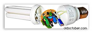
Energy saving lamps are gaining popularity. The European Union has already banned the production of conventional incandescent lamps. Unfortunately, energy-saving lamps sometimes fail too. They can, of course, be thrown away and forgotten. Or you can subject her to a hacking procedure. So, we disassemble a burnt out energy-saving lamp. Because, as a rule, only the threads in the bulb itself burn out, and the electronic components in the lamp base are operable with a probability of 99.9%.
To see what color the insides of an energy-saving lamp are, you need to open it. So as not to injure your hands on glass tubes (they are from thin glass and can burst at any time), wrap the flask in a plastic bag and grab it with tape. The place of gluing the body is obvious and we are trying to separate its parts with a screwdriver or a powerful knife. If we do it carefully, we will spend 2 minutes.
When the energy-saving lamp breaks down into three parts, the following picture will open to us:
As you can see, the main parts are a bulb, a board with electronic elements (radio components) and a lamp base. Now let's estimate what and how we can apply.
Energy-saving lamp bulb... Honestly, I have not yet figured out what to do with him. The flask is a sealed glass envelope coated with a phosphor from the inside. It will hardly be possible to open it painlessly. And using it as some kind of float is unreliable - glass is all the same.
Base / plinth. This item is already more attractive. He can be given a second life. After all, this is actually a small case, with a contact that can be screwed into any standard E27 or E14 cartridge.

The simplest application is that you can make an extension cord from this base (low-power, of course). Only it will be possible to turn it on not into an outlet, but into any cartridge. Perhaps the oldest generation remembers such devices. For some reason they were called "swindler". Such a kind of adapter "lamp-socket". By the way, it can be very useful in our time. Especially when traveling abroad. Since the system of design of sockets can be original and original in the country and it is not always possible to purchase or select an adapter for it, but you need to charge a mobile phone, laptop, navigator, camera.
Energy-saving lamps are widely used in everyday life and in production, over time they become unusable, and yet many of them can be restored after a simple repair. If the lamp itself is out of order, then a rather powerful power supply unit for any required voltage can be made from the electronic "filling".
What does a power supply unit look like from an energy-saving lamp
In everyday life, a compact, but at the same time, powerful low-voltage power supply is often required; this can be done using a failed energy-saving lamp. In lamps, lamps most often fail, and the power supply remains in working order.
In order to make a power supply, it is necessary to understand the principle of operation of the electronics contained in the energy-saving lamp.
Advantages of switching power supplies
In recent years, there has been a clear tendency to move away from classical transformer power supplies to switching power supplies. This is due, first of all, to the great disadvantages of transformer power supplies, such as large mass, low overload capacity, low efficiency.
The elimination of these shortcomings in switching power supplies, as well as the development of the element base, made it possible to widely use these power nodes for devices with a power from a few watts to many kilowatts.
Power supply circuit
The principle of operation of a switching power supply in an energy-saving lamp is exactly the same as in any other device, for example, a computer or TV.
In general terms, the operation of a switching power supply can be described as follows:
- AC mains current is converted to DC without changing its voltage, i.e. 220 V.
- A transistor pulse width converter converts DC voltage into rectangular pulses, with a frequency of 20 to 40 kHz (depending on the lamp model).
- This voltage is fed through the choke to the luminaire.
Consider the scheme and operation of the switching lamp power supply (figure below) in more detail.

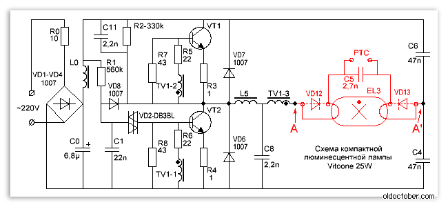
Energy-saving lamp electronic ballast circuit
The mains voltage is fed to the bridge rectifier (VD1-VD4) through a limiting resistor R 0 of small resistance, then the rectified voltage is smoothed on a filtering high-voltage capacitor (C 0), and through a smoothing filter (L0) is fed to the transistor converter.
The start of the transistor converter occurs at the moment when the voltage across the capacitor C1 exceeds the opening threshold of the VD2 dinistor. This will start the generator on transistors VT1 and VT2, due to which self-generation occurs at a frequency of about 20 kHz.
Other circuit elements such as R2, C8 and C11 play a supporting role in making it easier to start the generator. Resistors R7 and R8 increase the closing speed of the transistors.
And resistors R5 and R6 serve as limiting resistors in the base circuits of transistors, R3 and R4 protect them from saturation, and in case of breakdown play the role of fuses.
Diodes VD7, VD6 are protective, although in many transistors designed to work in such devices, such diodes are built-in.
TV1 - transformer, with its windings TV1-1 and TV1-2, voltage feedback from the output of the generator is fed into the base circuits of the transistors, thereby creating conditions for the operation of the generator.
In the figure above, the parts to be removed when reworking the block are highlighted in red, points А – А` must be connected with a jumper.
Alteration of the block
Before proceeding with the alteration of the power supply, you should decide on what current power you need to have at the output, the depth of modernization will depend on this. So, if a power of 20-30 W is required, then the alteration will be minimal and will not require much intervention in the existing circuit. If it is necessary to obtain a power of 50 or more watts, then a more thorough modernization will be required.
It should be borne in mind that the output of the power supply will be a constant voltage, not an alternating one. It is impossible to get an alternating voltage with a frequency of 50 Hz from such a power supply unit.
Determine the power
Power can be calculated using the formula:
Р - power, W;
I - current strength, A;
U - voltage, V.
For example, take a power supply with the following parameters: voltage - 12 V, current - 2 A, then the power will be:
Taking into account the overload, 24-26 W can be taken, so that for the manufacture of such a block, minimal intervention in the circuit of a 25 W energy-saving lamp is required.
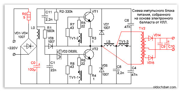
New parts

Adding new parts to the diagram
The added details are highlighted in red, these are:
- diode bridge VD14-VD17;
- two capacitors C 9, C 10;
- additional winding placed on the ballast choke L5, the number of turns is selected empirically.
The added winding to the choke plays another important role of the isolation transformer, preventing the mains voltage from entering the power supply output.
To determine required amount turns in the added winding, you should do the following:
- a temporary winding is wound on the inductor, about 10 turns of any wire;
- connected with a load resistance, with a power of at least 30 W and a resistance of about 5-6 ohms;
- include in the network, measure the voltage across the load resistance;
- the resulting value is divided by the number of turns, they find out how many volts are per 1 turn;
- calculate the required number of turns for a constant winding.
A more detailed calculation is given below.

Test inclusion of a converted power supply
After that, it is easy to calculate the required number of turns. To do this, the voltage that is planned to be obtained from this unit is divided by the voltage of one turn, the number of turns is obtained, and about 5-10% is added to the result.
W = U out / U vit, where
W is the number of turns;
U out - the required output voltage of the power supply;
U vit - voltage per one turn.

Winding an additional winding on a standard choke
The original choke winding is under mains voltage! When winding an additional winding over it, it is necessary to provide interwinding insulation, especially if a PEL-type wire is wound, in enamel insulation. For interwinding insulation, polytetrafluoroethylene tape can be used to seal threaded connections, which is used by plumbers, its thickness is only 0.2 mm.
The power in such a unit is limited by the overall power of the used transformer and the permissible current of the transistors.
High power power supply unit
This will require a more complex upgrade:
- additional transformer on a ferrite ring;
- replacement of transistors;
- installation of transistors on radiators;
- an increase in the capacity of some capacitors.
As a result of such an upgrade, a power supply unit with a capacity of up to 100 W is obtained, with an output voltage of 12 V. It is capable of providing a current of 8-9 amperes. This is enough to power, for example, a medium power screwdriver.
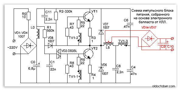
The diagram of the upgraded power supply is shown in the figure below.

100W power supply
As you can see in the diagram, the resistor R 0 is replaced with a more powerful (3-watt) resistor, its resistance is reduced to 5 ohms. It can be replaced with two 2-watt 10 ohms by connecting them in parallel. Further, C 0 - its capacity is increased to 100 microfarads, with an operating voltage of 350 V. If it is undesirable to increase the dimensions of the power supply, then you can find a miniature capacitor of such a capacity, in particular, it can be taken from a camera-soap dish.
To ensure reliable operation of the unit, it is useful to slightly reduce the values of the resistors R 5 and R 6, to 18-15 Ohm, and also to increase the power of the resistors R 7, R 8 and R 3, R 4. If the generation frequency turns out to be low, then the ratings of the capacitors C 3 and C 4 - 68n should be increased.
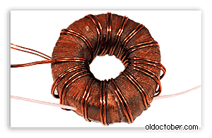
The most difficult thing can be making a transformer. For this purpose, in pulse units, ferrite rings of appropriate sizes and magnetic permeability are most often used.
Calculation of such transformers is rather complicated, but there are many programs on the Internet with which it is very easy to do, for example, "Lite-CalcIT Pulse Transformer Calculation Program".
![]()
What a pulse transformer looks like
The calculation carried out using this program gave the following results:
A ferrite ring is used for the core, its outer diameter is 40, the inner diameter is 22, and the thickness is 20 mm. The primary winding with a PEL wire - 0.85 mm 2 has 63 turns, and two secondary windings with the same wire - 12.
The secondary winding must be wound in two wires at once, while it is advisable to pre-twist them slightly along the entire length, since these transformers are very sensitive to the asymmetry of the windings. If this condition is not observed, then the VD14 and VD15 diodes will heat up unevenly, and this will further increase the asymmetry, which, in the end, will disable them.
But such transformers easily forgive significant errors when calculating the number of turns, up to 30%.
Since this circuit was originally designed to work with a 20 W lamp, transistors 13003 are installed. In the figure below, position (1) is medium power transistors, they should be replaced with more powerful ones, for example, 13007, as in position (2). You may need to install them on metal plate(radiator), with an area of about 30 cm 2.

Trial
A test turn-on should be carried out with the observance of some precautions so as not to damage the power supply:
- Make the first test switch on through a 100 W incandescent lamp to limit the current to the power supply.
- It is imperative to connect a 3-4 Ohm load resistor to the output, with a power of 50-60 W.
- If everything went well, let it run for 5-10 minutes, turn off and check the degree of heating of the transformer, transistors and rectifier diodes.
If no mistakes were made during the replacement of parts, the power supply should work without problems.
If the test turn-on showed the unit to work, it remains to test it in full load mode. To do this, reduce the resistance of the load resistor to 1.2-2 Ohm and connect it directly to the network without a light bulb for 1-2 minutes. Then turn off and check the temperature of the transistors: if it exceeds 60 0 C, then they will have to be installed on the radiators.
Technical information: → Make a power supply from a burnt out energy-saving lamp
This publication contains material for the repair or manufacture of switching power supplies of different power based on the electronic ballast of a compact fluorescent lamp.
You can make a switching power supply for 5 ... 20 watts in a short time. It can take up to several hours to manufacture a 100-watt power supply.
It will be easy to build a power supply for those who know how to solder. And undoubtedly, this is easy to do than to find a low-frequency transformer of the required power suitable for manufacturing and rewind its secondary windings to the required voltage.

V recent times Compact Fluorescent Lamps (CFLs) have become widespread. To reduce the size of the ballast choke, they use a high-frequency voltage converter circuit, which can significantly reduce the size of the choke.
In the event of a failure of the electronic ballast, it can be easily repaired. But, when the bulb itself fails, the bulb has to be thrown away.
However, the electronic ballast of such a light bulb is an almost ready-made switching power supply unit (PSU). The only thing that the electronic ballast circuit differs from a real pulsed power supply unit is the absence of an isolation transformer and a rectifier, if necessary.

Recently, radio amateurs sometimes have difficulty finding power transformers to power their homemade designs... Even if a transformer is found, then rewinding it requires the use of copper wires of the required diameter, and the mass-dimensional parameters of products assembled on the basis of power transformers are not particularly pleasing. But in the overwhelming majority of cases, a power transformer can be replaced with a pulsed power supply. If, for these purposes, ballast from faulty CFLs is used, then the savings will amount to a certain amount, especially when it comes to transformers of 100 watts or more.
The difference between a CFL circuit and a pulsed power supply unit.
This is one of the most common electrical circuits energy saving lamps. To convert the CFL circuit into a pulse power supply, you need to install only one jumper between points A - A 'and add a pulse transformer with a rectifier. Items that can be deleted are marked in red.
And this is an already completed circuit of a pulse power supply, assembled on the basis of CFLs using an additional pulse transformer.
For simplicity, the fluorescent lamp and a few parts have been removed and replaced with a jumper.
As you can see, the CFL circuit does not require major changes. Additional elements introduced into the scheme are marked in red.
What power supply unit can be made from CFL?
The power of the power supply is limited by the overall power of the pulse transformer, the maximum permissible current of the key transistors and the size of the cooling radiator, when used.
A low-power power supply can be built by winding the secondary winding directly onto the frame of an existing choke from the lamp unit.
If the choke window does not allow winding the secondary winding or if you need to build a power supply unit with a power that significantly exceeds the CFL power, then you will need an additional pulse transformer.
If you need to get a power supply with a power of more than 100 watts, and you use ballast from a 20-30 watt lamp, then most likely you will have to make minor changes to the electronic ballast circuit.
In particular, it may be necessary to install more powerful VD1-VD4 diodes in the input bridge rectifier and rewind the input choke L0 with a thicker wire. If the current gain of the transistors is insufficient, then the base current of the transistors will have to be increased by reducing the values of the resistors R5, R6. In addition, you will have to increase the power of the resistors in the base and emitter circuits.
If the generation frequency is not very high, then it may be necessary to increase the capacitance of the blocking capacitors C4, C6.
Pulse transformer for power supply.

A feature of self-excited half-bridge switching power supplies is the ability to adapt to the parameters of the used transformer. And the fact that the feedback loop will not pass through our homemade transformer makes the task of calculating the transformer and setting up the unit even easier. Power supplies assembled according to these schemes forgive errors in calculations up to 150% and higher.
To increase the power of the power supply, we had to wind the TV2 pulse transformer. In addition, I increased the capacitance of the mains voltage filter C0 to 100µF.

Since the efficiency of the power supply is not at all 100%, it was necessary to fasten some radiators to the transistors.
After all, if the efficiency of the unit is even 90%, you will still have to dissipate 10 watts of power.
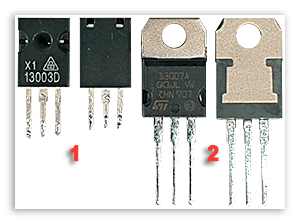
I was not lucky, in my electronic ballast transistors 13003 pos. 1 of such a design were installed, which, apparently, is designed to be attached to the radiator using shaped springs. These transistors do not need spacers, since they are not equipped with a metal pad, but they also give off heat much worse. I replaced them with transistors 13007 pos. 2 with holes so that they could be screwed to the radiators with ordinary screws. In addition, 13007 have several times higher maximum permissible currents.
If you wish, you can safely screw both transistors onto one radiator. I checked it works.

Only, the cases of both transistors must be isolated from the heatsink case, even if the heatsink is inside the case. electronic device.
It is convenient to fasten it with M2.5 screws, on which you must first put on insulating washers and pieces of insulating tube (cambric). It is allowed to use KPT-8 heat-conducting paste, since it does not conduct current.

Attention! The transistors are under mains voltage, so the insulating gaskets must ensure electrical safety conditions!
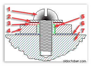
The drawing shows the connection of a transistor with a cooling radiator in section.
- Screw M2.5.
- Washer М2.5.
- Insulating washer М2,5 - fiberglass, textolite, getinax.
- Transistor housing.
- The gasket is a piece of tube (cambric).
- Gasket - mica, ceramics, fluoroplastic, etc.
- Cooling radiator.

And this is a working one-hundred-watt switching power supply.
The dummy load resistors are immersed in water as their power is insufficient.
The power allocated to the load is 100 watts.
Self-oscillation frequency at maximum load - 90 kHz.
Self-oscillation frequency without load - 28.5 kHz.
The temperature of the transistors is 75ºC.
The radiator area of each transistor is 27 cm².
Choke temperature TV1 - 45ºC.
TV2 - 2000NM (Ø28 x Ø16 x 9mm)
Rectifier.
All secondary rectifiers of a half-bridge switching power supply must be full-wave. If this condition is not met, then the magnetic conductor may enter saturation.

There are two common full-wave rectifier circuits.
1. Bridge scheme.
2. Scheme with a zero point.
The bridge circuit saves a meter of wire, but dissipates twice as much energy on the diodes.
The zero point circuit is more economical, but requires two perfectly symmetrical secondary windings. Asymmetry in the number of turns or location can lead to saturation of the magnetic circuit.
However, it is the zero-point circuits that are used when it is required to obtain large currents at a low output voltage. Then, for additional minimization of losses, instead of conventional silicon diodes, Schottky diodes are used, on which the voltage drop is two to three times less.
Example.
Rectifiers of computer power supplies are made according to the zero point scheme. With a power output of 100 watts and a voltage of 5 volts, 8 watts can dissipate even on Schottky diodes.
100/5 * 0.4 = 8 (Watt)
If we use a bridge rectifier, and even ordinary diodes, then the power dissipated on the diodes can reach 32 watts or even more.
100/5 * 0.8 * 2 = 32 (Watt).
Pay attention to this when you design the power supply, so that later you do not look for where half the power disappeared.
In low voltage rectifiers, it is better to use a zero point circuit. Moreover, with manual winding, you can simply wind the winding in two wires. In addition, high-power switching diodes are not cheap.
How to properly connect the switching power supply to the network?

To set up switching power supplies, they usually use the following connection scheme. Here the incandescent lamp is used as a ballast with a non-linear characteristic and protects the UPS from failure during abnormal situations. The power of the lamp is usually chosen close to the power of the pulsed power supply under test.
When a pulsed power supply unit is operating at idle or at a low load, the resistance of the lamp cocoa filament is low and it does not affect the operation of the unit. When, for some reason, the current of the key transistors increases, the spiral of the lamp becomes heated and its resistance increases, which leads to the limitation of the current to a safe value.

This drawing shows a diagram of a stand for testing and adjusting pulsed power supplies that meets electrical safety standards. The difference between this circuit and the previous one is that it is equipped with an isolation transformer, which provides galvanic isolation of the investigated UPS from the lighting network. The SA2 switch allows you to block the lamp when the power supply delivers more power.
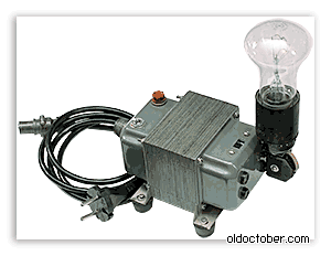
And this is already an image of a real stand for repair and adjustment of pulsed power supplies, which I made many years ago according to the diagram above.
An important operation when testing a PSU is a dummy load test. It is convenient to use powerful resistors such as PEV, PPB, PSB, etc. as a load. These "glass ceramic" resistors are easy to find on the radio market for their green coloring. Red numbers are power dissipation.

It is known from experience that for some reason the power of the equivalent load is always not enough. The resistors listed above can dissipate power two to three times the nominal for a limited time. When the power supply unit is turned on for a long time to check thermal conditions, and the power of the equivalent load is insufficient, then the resistors can simply be dipped into the water.
Be careful not to burn!
Terminating resistors of this type can heat up to a temperature of several hundred degrees without any external manifestations!
That is, you will not notice any smoke or discoloration and you can try to touch the resistor with your fingers.
How to set up a switching power supply?
Actually, the power supply, assembled on the basis of a serviceable electronic ballast, does not require special adjustment.
It must be connected to the dummy load and make sure that the PSU is capable of delivering the rated power.
During a run under maximum load, you need to follow the dynamics of the temperature rise of transistors and transformer. If the transformer heats up too much, then you need to either increase the wire cross-section, or increase the overall power of the magnetic circuit, or both.
If the transistors are very hot, then you need to install them on the radiators.
If a home-wound choke from CFL is used as a pulse transformer, and its temperature exceeds 60 ... 65 ° C, then it is necessary to reduce the load power.
It is not recommended to raise the temperature of the transformer above 60… 65 ° C, and of transistors above 80… 85 ° C.
What is the purpose of the elements of the switching power supply circuit?
R0 - limits the peak current flowing through the rectifier diodes at the moment of switching on. In CFLs, it also often acts as a fuse.
VD1… VD4 is a bridge rectifier.
L0, C0 - power filter.
R1, C1, VD2, VD8 - converter start circuit.
The launch node works as follows. Capacitor C1 is charged from the source through resistor R1. When the voltage across the capacitor C1 reaches the breakdown voltage of the dinistor VD2, the dinistor unlocks itself and unlocks the transistor VT2, causing self-oscillations. After the onset of generation, rectangular pulses are applied to the cathode of the VD8 diode and the negative potential reliably blocks the VD2 dinistor.
R2, C11, C8 - make it easier to start the converter.
R7, R8 - improve the blocking of transistors.
R5, R6 - limit the base current of the transistors.
R3, R4 - prevent saturation of transistors and act as fuses during breakdown of transistors.
VD7, VD6 - protect transistors from reverse voltage.
TV1 is a feedback transformer.
L5 - ballast choke.
C4, C6 - blocking capacitors, on which the supply voltage is halved.
TV2 is a pulse transformer.
VD14, VD15 - pulse diodes.
C9, C10 - filter capacitors.
Energy saving light bulbs are widely used both for household and industrial purposes. Over time, any lamp becomes faulty. However, if desired, the luminaire can be reanimated by assembling the power supply from an energy-saving lamp. In this case, the filling of a failed light bulb is used as the components of the block.
Pulse block and its purpose
There are electrodes, an anode, and a cathode at both ends of the fluorescent tube. Applying power will heat up the lamp components. After heating, electrons are released, which collide with mercury molecules. The consequence of what is happening is ultraviolet radiation.

Due to the presence of a phosphor in the tube, the phosphor is converted into the visible glow of the lamp. The light does not appear immediately, but after a certain period of time after connecting to the mains. The more the luminaire is developed, the longer the interval.
The operation of a switching power supply unit is based on the following principles:
- Transformation alternating current from the mains to the constant. In this case, the voltage does not change (that is, 220 V remains).
- Transformation of DC voltage into rectangular pulses due to the operation of a pulse-width converter. The pulse frequency is 20 to 40 kHz.
- Supply voltage to the luminaire by means of a choke.

A source uninterruptible power supply(UPS) consists of a number of components, each of which is labeled in the circuit:
- R0 - plays a limiting and protective role in the power supply. The device prevents and stabilizes excessive current flowing through the diodes at the time of connection.
- VD1, VD2, VD3, VD4 - act as rectifier bridges.
- L0, C0 - are filters for the transmission of electric current and protect against voltage surges.
- R1, C1, VD8 and VD2 - represent a chain of converters used at startup. The first resistor (R1) is used to charge the capacitor C1. As soon as the capacitor breaks through the dinistor (VD2), it and the transistor open, as a result of which self-oscillation begins in the circuit. Next, a rectangular pulse is sent to the diode cathode (VD8). A minus indicator appears, overlapping the second dinistor.
- R2, C11, C8 - make it easier to get started with converters.
- R7, R8 - optimize the closing of the transistors.
- R6, R5 - form the boundaries for the electric current on transistors.
- R4, R3 - used as fuses for voltage surges in transistors.
- VD7 VD6 - protect power supply transistors from return current.
- TV1 is a reverse communication transformer.
- L5 - ballast choke.
- C4, C6 - act as decoupling capacitors. Divide all tension into two parts.
- TV2 is a pulse transformer.
- VD14, VD15 - pulse diodes.
- C9, C10 - filter capacitors.
Note! In the diagram below, the components that need to be removed when redoing the block are marked in red. Points A-A combined with a jumper.
Only a thoughtful selection of individual elements and their correct installation will allow you to create an efficiently and reliably working power supply.
Differences between a lamp and a pulse unit
The economy lamp circuit is in many ways reminiscent of the structure of a switching power supply. That is why it is not difficult to make a pulsed power supply unit. To remake the device, you will need a jumper and an additional transformer that will generate pulses. The transformer must have a rectifier.
To make the PSU lighter, the glass fluorescent light bulb is removed. The power parameter is limited to the highest throughput transistors and sizes of cooling elements. To increase the power, it is necessary to wind an additional winding around the choke.

Alteration of the block
Before you start altering the power supply unit, you must select the current output power. The degree of system modernization depends on this indicator. If the power is in the range of 20-30 W, no deep changes in the circuit are needed. If a power of more than 50 W is planned, a more systemic upgrade is needed.
Note! There will be constant voltage at the output from the PSU. It is not possible to obtain an alternating voltage at a frequency of 50 Hz.
Determination of power
The calculation of power is carried out according to the formula:

As an example, consider the situation with a power supply that has the following characteristics:
- voltage - 12 V;
- current strength - 2 A.
We calculate the power:
P = 2 × 12 = 24 W.
The final power parameter will be higher - about 26 W, which allows us to take into account possible overloads. Thus, to create a power supply, a rather minor intervention in the circuit of a standard 25 W economy lamp is required.
New components

New electronic components include:
- diode bridge VD14-VD17;
- 2 capacitors C9 and C10;
- a winding on a ballast choke (L5), the number of turns of which is determined empirically.
The additional winding performs another important function - it is an isolating transformer and protects against voltage penetration into the UPS outputs.
To calculate the required number of turns in the additional winding, the following actions are performed:
- Temporarily apply a winding to the inductor (approximately 10 turns of wire).
- We join the winding with a load resistance (power from 30 W and resistance 5-6 Ohm).
- We connect to the network and measure the voltage at the load resistance.
- Divide the result by the number of turns and find out how many volts are there for each turn.
- We find out the required number of turns for a permanent winding.
The calculation procedure is shown in more detail below.
To calculate the required number of turns, the planned voltage for the block is divided by the voltage of one turn. As a result, we get the number of turns. It is recommended to add 5-10% to the final result, which will allow you to have a certain margin.

Do not forget that the original choke winding is under mains voltage. If you need to wind a new layer of winding around it, take care of the interwinding insulating layer. It is especially important to observe this rule when applying a PEL-type wire in enamel insulation. A polytetrafluoroethylene tape (0.2 mm thick) is suitable as an interwinding insulating layer, which will increase the density of threaded connections. This tape is used by plumbers.
Note! The power in the unit is limited by the overall power of the involved transformer, as well as by the maximum possible current of the transistors.
Self-made power supply
The UPS can be made by hand. This will require small changes to the jumper of the electronic choke. Next, it is connected to a pulse transformer and a rectifier. Individual elements of the circuit are deleted due to their uselessness.
If the power supply is not too high-power (up to 20 W), it is not necessary to install a transformer. A few turns of a conductor wound on a magnetic circuit located on the ballast of a light bulb will suffice. However, this operation can only be carried out if there is sufficient space for the winding. For it, for example, an MGTF-type conductor with a fluoroplastic insulating layer is suitable.

Usually, not so many wires are needed, since almost the entire gap of the magnetic circuit is given to the insulation. It is this factor that limits the capacity of such units. To increase the power, a pulse-type transformer is required.
A distinctive characteristic of this type of SMPS (switching power supply) is the ability to adjust it to the characteristics of the transformer. In addition, there is no feedback loop in the system. The connection diagram is such that there is no need for particularly accurate calculations of the transformer parameters. Even if a gross error is made in the calculations, the uninterruptible power supply is likely to function.
A pulse transformer is created on the basis of a choke, on which a secondary winding is superimposed. As such, a varnished copper wire is used.
The interwinding insulating layer is most often made of paper. In some cases, a synthetic film is applied to the winding. However, even in this case, you should additionally secure yourself and wind 3-4 layers of special electrical protective cardboard. In extreme cases, paper with a thickness of 0.1 millimeter or more is used. Copper wire is applied only after this safety measure is provided.
![]()
As far as the diameter of the conductor is concerned, it should be as large as possible. The number of turns in the secondary winding is small, so a suitable diameter is usually chosen by trial and error.
Rectifier
To prevent saturation of the magnetic circuit in the uninterruptible power supply, only full-wave output rectifiers are used. For a pulse transformer operating to reduce the voltage, a circuit with a zero mark is considered optimal. However, for it you need to make two absolutely symmetrical secondary windings.
For a switching uninterruptible power supply, a conventional rectifier operating according to the diode bridge circuit (on silicon diodes) is not suitable. The fact is that for every 100 watts of transported power, the losses will be at least 32 watts. If you make a rectifier from powerful pulse diodes, the costs will be high.
Setting up an uninterruptible power supply
When the power supply is assembled, it remains to connect it to the largest load to check if the transistors and transformer overheat. The temperature maximum for a transformer is 65 degrees, and for transistors - 40 degrees. If the transformer heats up too much, you need to take a conductor with a large cross-section or increase the overall power of the magnetic circuit.

The listed actions can be performed simultaneously. For transformers from choke balances, it is most likely that it will not be possible to increase the conductor cross-section. In this case, the only option is to reduce the load.
High power UPS
In some cases, the standard ballast capacity is not sufficient. As an example, let's take the following situation: you have a 24 W lamp and you need a UPS for charging with 12 V / 8 A.
To implement the scheme, you will need an unused computer power supply. We take out the power transformer from the block together with the R4C8 circuit. This circuit protects the power transistors from overvoltage. We connect the power transformer to the electronic ballast. In this situation, the transformer replaces the choke. Below is an assembly diagram of an uninterruptible power supply based on a housekeeper light bulb.

It is known from practice that this type of unit makes it possible to receive up to 45 W of power. Heating of transistors is within normal limits, not exceeding 50 degrees. To completely eliminate overheating, it is recommended to mount a transformer with a large core section into the transistor bases. The transistors are placed directly on the radiator.
Potential errors
It makes no sense to simplify the circuit by imposing the base windings directly on the power transformer. In the absence of a load, considerable losses will occur, since a large current will flow into the transistor bases.
If a transformer is used with an increase in the load current, the current in the transistor bases will also increase. It is empirically established that after the load indicator reaches 75 W, saturation occurs in the magnetic circuit. The result is a decrease in the quality of transistors and their excessive heating. In order to prevent such a development of events, it is recommended to independently wind the transformer using a larger section of the core. It is also allowed to fold two rings together. Another option is to use a larger conductor diameter.
![]()
The basic transformer acting as an intermediate link can be removed from the circuit. For this purpose, the current transformer is connected to the dedicated winding of the power transformer. This is done using a high-power resistor based on a feedback circuit. The disadvantage of this approach is the constant operation of the current transformer under saturation conditions.
It is inadmissible to connect a transformer together with a choke (located in the ballast converter). Otherwise, the frequency of the UPS will increase due to a decrease in the total inductance. This will result in losses in the transformer and excessive heating of the rectifier transistor at the output.
We must not forget about the high responsiveness of diodes to increased rates of reverse voltage and current. For example, if you put a 6-volt diode in a 12 volt circuit, given element will quickly become unusable.

Do not replace transistors and diodes with low quality electronic components. The performance characteristics of the Russian-made element base leave much to be desired, and the result of the replacement will be a decrease in the functionality of the uninterruptible power supply.